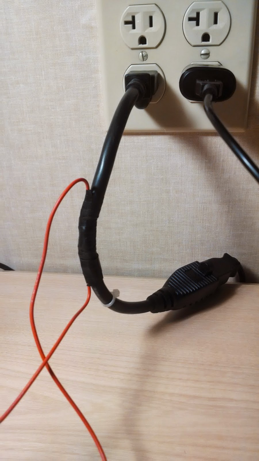
I'll detail the wiring and components below, but first I'll explain what I hope to accomplish with something like this. I'm focused first on designing a self-contained lighting control system for my master bathroom. To do it, I need circuitry that can let my software:
- Tell how much light is present. There's no need to turn on the light if there's enough daylight present. This is for general bathroom lighting; it may make sense to turn additional lights on over the sink for putting on makeup, for example, but I'm assuming that sort of thing will be manual.
- Tell if the "door" is closed. This is both to help with determining if someone is present and to decide when to turn the light on at night.
- Tell if someone is moving in view of the PIR (assuming the PIR works), to help determine if someone is present.
- Turn the light on and off.
This all worked great (except that I had to simulate the PIR, since it wasn't working).
One other tweak I threw in was to change the behavior when the light sensor detected intermediate light levels. If the bathroom is pitch black, that means it's night time and turning on the lights when the door is open is a bad idea. If the bathroom is very light, there's no need to turn them on at all. In between, it may make sense to turn them on, but there's no need to worry about blasting someone in the bedroom with light because it won't increase the brightness that much. Actually, the ideal way to evaluate that is with an additional light sensor in the bedroom -- which I plan to have, though it will probably be connected to the Arduino in that room, so the central automation controller will have to route that signal.
I altered the logic to include handling of this intermediate light state and it worked very nicely in my testing.
BTW, the idea of routing the light status from the bedroom sensor through the central controller to the bathroom controller is a good example of one thing I want to be careful to achieve: I'm fine with some degraded functionality if the individual room controllers are operating independently, but I think they should have enough local intelligence to operate reasonably well. For example, fairly simple light control logic should work, including honoring light on/off requests from the light switches. Inter-room cooperation is nice, but I don't want to have to cross-connect the rooms directly, so all of that will go through the central controller, which will also enable much more intelligent control, including remote control through web and mobile apps, etc.
Anyway, here are the details:
Here's the schematic, without the PIR:
And here's the actual breadboarded circuit (with the PIR):
The relay portion is single-pole, double-throw with 3V coil (needs at least 3V to activate) and can handle up to 10A through the circuit. I used 5V to activate it, with a transistor to switch the coil because the coil draws about 160 mA and the Arduino Uno's data pins can only supply 40 mA. There's also a 220Ω (ish; I think the actual resistor was 270Ω) resistor to limit the current to the transistor base. Pin 12 on the Arduino, configured for OUTPUT, was connected to the resistor and then to the transistor base, so powering that pin switches the relay.
I wired the neutral line of a one-foot extension cord across the normally-open poles of the relay, so activating the relay closes the circuit, then I plugged the extension into the wall and to a desk lamp.
The red wire is 18 AWG solid which, according to the charts I find online, should be good for up to 14A of 120 VAC, so that's safe-ish, though a real circuit should have a 10A fuse. A real circuit should also not leave the relay poles exposed where someone could touch them, and should be soldered or screwed!
The phototransistor's negative side was connected to ground through a resistor, essentially a pull-down, and the positive side connected directly to 5V, and also to the the A0 analog input pin on the Arduino, configured as an INPUT pin. By varying the size of the resistor I could control the amount of light that triggered different input levels on A0. I need to think about what exactly that resistor was doing, electrically -- I'm still not 100% clear on how pulldowns and pullups work.
The magnetic switch is the simplest: One wire is connected to ground and the other to pin 4, configured as INPUT_PULLUP. Putting the magnet by the reed switch (within about 1/2 inch) causes the reed switch to close and the pin to read LOW. Moving it away opens the switch and causes the pin to read HIGH.
The PIR sensor circuit is also trivial to wire: three pins one goes to +5V, one to ground and the last is a data pin which should go HIGH whenever the device sees movement. There is a calibration needed at power up, but that basically consists of waiting 30 seconds before trying to read it. But my data pin never went HIGH. Dunno.
I'll add the code later, since I want to clean it up a little before posting it.


No comments:
Post a Comment